Remote Temperature Monitoring Using Meshtastic
- Date published: 2025-07-15
- Date updated: 2025-07-15
Background
A project that has been I have been working on and off for awhile is a temperature monitor for K9 units, i.e. vehicles that carry dogs around. There is a large amount of (justified) stigma around leaving your dog in your car. However, there are ways to mitigate the risk of your dog being injured from heat exposure in a vehicle, and one of the best ones is to have live reporting of temperature while you are away. For people that constantly travel with their dogs, this is an essential system that unfortunately is not easy to obtain on a budget. Crash-rated dog kennels are already a significant investment for many people and adding the cost of temperature monitoring is generally out of reach for many people.
The market for remote temperature monitoring of K9 units is segmented into two main categories:
- Professional units
- Usually integrated into the vehicles systems for power and engine/air conditioning control
- Often monitored via a cellular network, in the case of first responder units, it can be tied to their existing vehicle network connection
- Very expensive to purchase and install; $1,000 or more for materials alone along with a complex installation process that may be incompatible with uncommon vehicles
- Consumer units
- Generally not integrated into vehicle systems
- Monitored via cellular using a subscription model or a Bluetooth/WiFi close-range device
- Cheaper to install but a subscription is often required to monitor via cellular
When approaching this project I wanted to create a simple, low cost, battery powered device that could be monitored remotely. My first thought for this was to use a cellular modem development board. However, there are few programming tasks that are more annoying than dealing with cellular modems. My next approach was to create two simple wireless devices where one would act as a sensor and the other as a "pager". Given my past use of LoRa (a RF protocol specialized for long range) development boards, I ended up landing on Meshtastic for the wireless communication method for this project.
Cellular modem experiments
I started this project with the purchase of a cellular development board, the iLabs Challenger RP2040 LTE MkII. While I have worked with cellular modems in the past, particularly setting up simple FTP services. I have never worked with UBLOX modems, nor on have I done it with a microcontroller. I feel that I have gathered enough experience in this field to comfortably say that I hate cellular modems. While UBLOX has expansive data sheets and handbooks for all of their products, and they are widely accepted to have some of the easiest to use modems in the IoT world, the institutional knowledge needed to get one of these modems working is staggering.
I attempted to lean on the available open-source crates such as ublox-cellular-rs. While the developers have done a fantastic job with this crate, it is for their commercial use. As with much embedded software, once it is running it is generally left alone. The employees of FactBird maintaining this crate did work with me to get it working for my application. However, they had no reason to spend paid development time to adapt their code to a modem they have zero intention of using. Either way, they were very polite and helpful but the will to program for these modems is generally exhausted the moment the minimum functionality is reached. There are few resources for a general purpose libraries like you would see for other things like sensors or small displays.
At this point I had two choices: fork the existing crates and adapt them to my modem, or give up and switch approaches. I decided, for my sanity, and because this was a hobby project, to swap my approach away from cellular and towards more local wireless solutions. This decision does come with some benefits, namely simplicity of the infrastructure needed and that that cellular service was no longer a requirement for use. The primary downside of this switch is that range will be limited and the end user will have to carry a secondary device to monitor the vehicle.
Re-discovering Meshtastic
As part of another project, I had three Lilygo T-Beam development boards laying around. Previously I wrote the firmware myself and while that is still a viable option, I decided to go with an open-source option for this project. A few years ago, when I had first looked at Meshtastic, I dismissed it because of its instability, lack of proper documentation, and features. This time around, however, Meshtastic has improved drastically and has become a very useful tool for collection of IoT sensor data and mesh communication.
Flashing the latest version of Meshtastic to my T-Beam nodes was a simple matter using their online flash tool and web-serial. A few experiments confirmed the boards' range and that they would be more than sufficient for this application. I even flew across the country and got multiple mesh connections at 30,000ft (this is a joke, if you are the FAA). These boards were not as power efficient or as sensitive as some of the new Meshtastic hardware being released today but they are more than sufficient for a proof of concept.
One downside to the existing hardware I had was that they utilized slightly older LoRa transceivers which appear to have a firmware/hardware bug that will not be getting fixed any time soon, see this issue and this issue for more details. More on this later. Other than that, however, I have not seen anything else to degrade my confidence in the system as of yet, Meshtastic is a well-maintained shining example of what an open source project can be.
Creating a bolt-on sensor module
Meshtastic is a project to create mesh communication devices for people, not sensors. While the firmware does have provisions for using many different types of sensors for environment monitoring, it does not support user interaction with those sensors from another node, real-time feedback, and notifications. In order to do this you could add your own module into the Meshtastic source code, see the docs for Meshtastic modules here. This approach is generally discouraged in the docs and instead the Serial module is preferred, see the docs here. In order to utilize the serial module, a second microcontroller running a totally independent binary is necessary. This approach is wasteful of power and material but is does greatly simplify programming as the hard parts of radio communication are totally off-loaded.
For this project, I chose to use the Pi Pico because I keep them on hand, however, if I had to do this at scale I would choose the smallest controller I could with low power modes to extend the sensor node's battery life. The only interfaces needed are a UART and I2C, even a 10 cent CH32V003 would be more than capable of running the code (though its limited flash size of 16KB might mean I have to rewrite the code to fit). As an aside, the binary size for the sensor module is 1.5MB at the time of writing which is, ever so slightly, wildly bloated. While it is possible to write compact Rust code, much of the benefits of the Rust ecosystem in embedded, e.g. dependency management and async via Embassy, can easily waste large amounts of binary size.
The general plan was to create a module that would accept commands over the network via a simple text interface. The available commands would be as follows:
- help or h: Display a help message of some kind
- temp or t: Get the current measured temperature
- test: Sends a test alert message
- state or s: Display a summary of the device state values
- pause or p: Pause periodic temp updates, does not disable warnings
- resume or r: Resume periodic temp updates
- set and get: Allow you to read or write a control value to control the device, available fields are:
- minimum or min: Low temp warning threshold e.g. set min 20 or get minimum
- maximum or max: High temp warning threshold e.g. set max 76 or get maximum
- update: Minutes per periodic temp update e.g. set update 0.5 or get update
- sense: seconds per temp sensor check e.g. set sense 10 or get sense
Parsing Meshtastic serial messages
The first step of creating a CLI-like interface over serial is to actually parse the input from Meshtastic. The messages sent to the controller are of a standard format that is seemingly not very well documented. Note this is discussing "text mode" and not protobuf mode. While protobuf mode would have definitely given me more control, for this simple an application it did not seem like the juice was worth the squeeze. The message format is as follows:
[some junk]: [actual message]\r\n
I wrote a rudimentary parser that accumulates data until the end sequence is found and returns just the extracted string of interest.
async fn get_command(rx: &mut BufferedUartRx<'_, UART1>) -> String<COMMAND_BUFFER_SIZE> {
    let mut command_buf = [0; COMMAND_BUFFER_SIZE];
    let mut cursor = 0;
    loop {
        if cursor >= command_buf.len() {
            command_buf.fill(0);
            cursor = 0;
        }

        let r = rx
            .read(&mut command_buf[cursor..])
            .await
            .expect("Failed to read UART");
        cursor += r;

        // Ignore everything after end sequence
        if let Some(end) = command_buf.windows(2).position(|p| p == b"\r\n") {
            // Ignore everything before start sequence
            if let Some(mut start) = command_buf[..end].windows(2).position(|p| p == b": ") {
                start += 2;
                let v: Vec<u8, COMMAND_BUFFER_SIZE> =
                    Vec::from_slice(&command_buf[start..end]).unwrap();

                let Ok(s) = String::from_utf8(v) else {
                    warn!("Failed to parse input as UTF-8");
                    command_buf.fill(0);
                    cursor = 0;
                    continue;
                };

                return s;
            }
            warn!("Found end sequence without start");
            command_buf.fill(0);
            cursor = 0;
        }
    }
}
This kind of simple parser is a great example of the power of async for embedded systems. If this function had to avoid blocking it would be difficult to accumulate data in the same way without resorting to some form of static storage. When the function is written using async, the programmer's intent remains clear and the moments where we yield to other tasks are clear, in this case just when waiting for additional UART bytes. Async allows for fairly complex non-blocking code to be written without having to pollute the data types utilized with static or guarded counterparts.
After the command was extracted from the UART buffer, it is passed to a lexxer mader with logos for tokenization. The Logos crate is easy to use and works well in a no_std environment with heapless types. The lexxing itself was done in just a few tokens for different key words, from the list of tokens the rest was just pattern matching. One thing to keep in mind is now Logos keeps track of which token matches when two tokens can both match. Manual priorities were set for my wildcards to ensure they do not consume my keywords. The struct with Logos declarative macros is shown below, the pattern matching on this enum has been left out for brevity but the full source code for this project will be linked at the end of this post.
#[derive(Logos, Debug, PartialEq)]
#[logos(skip r"[ \t\n\f]+")] // Ignore this regex pattern between tokens
enum Token {
    #[token("h")]
    #[token("help")]
    Help,

    #[token("t")]
    #[token("temp")]
    GetTemp,

    #[token("s")]
    #[token("state")]
    GetState,

    #[token("p")]
    #[token("pause")]
    Pause,

    #[token("r")]
    #[token("resume")]
    Resume,

    // Set and Get act as modifiers for state fields
    #[token("set")]
    Set,
    #[token("get")]
    Get,

    // State fields
    #[token("min")]
    #[token("minimum")]
    MinTemp,

    #[token("m")]
    #[token("max")]
    #[token("maximum")]
    MaxTemp,

    #[token("update")]
    Update, // Minutes per periodic update

    #[token("sense")]
    Sense, // Seconds per sensor temp check

    // Generic non-commands
    #[regex("[+-]?([0-9]+([.][0-9]*)?|[.][0-9]+)", priority = 1)]
    Number,

    #[regex("[a-zA-Z0-9]+", priority = 0)]
    Text,
}
Temperature sensing
I selected the Microchip MCP9808 I2C temperature sensor for the this project mainly because of its price and availability with an easy to integrate breakout board. The embedded-devices crate provided a wrapper around the I2C interface supplied by Embassy. The only thing out of the ordinary I did with this sensor was power it using a GPIO so it could be fully powered off between readings. The Quiic connector present on the breakout board I purchased did not expose the notification pin meaning I could not wake the RP2040 from sleep with an interrupt. While I could have routed an additional wire for that functionality I decided that it would mean commands sent from the user to the sensor module would only be answered if they happened to arrive in the exact moment of a temperature alarm. It is also worth mentioning that the low-power modes on the RP2040 suck and aren't worth a ton of effort to set up.
This part of the project was surprisingly easy and did not take any additional steps. I wish I had used a board with a Quiic connector so I did not have to solder the connections manually but at the end of the day the "hobbiest connectors" like Quiic and Grove are just standardized connectors for I2C busses. I am looking forward to using the embedded-devices crate more and possibly contributing to it if I run across something it does not support.
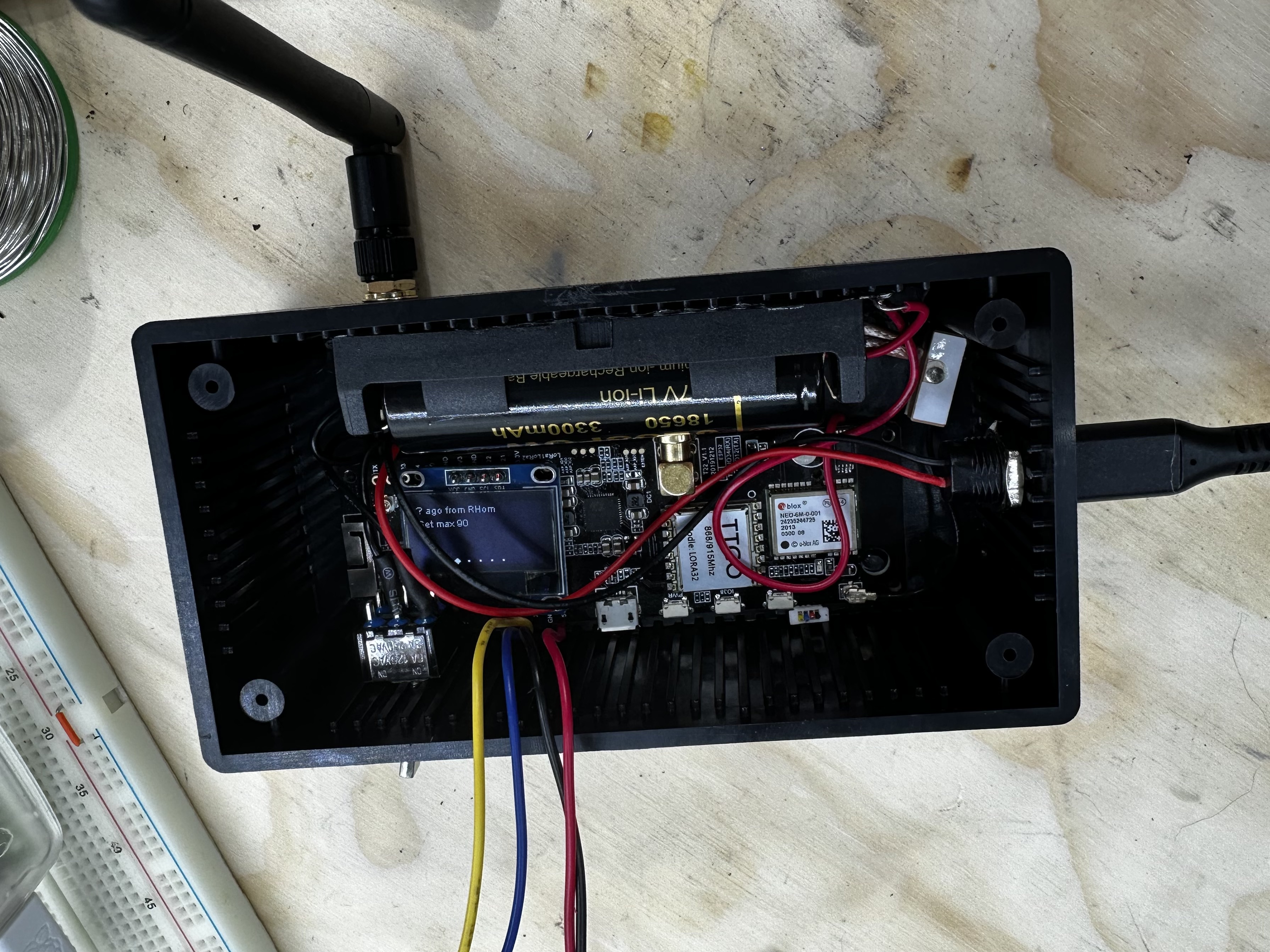
Hardware assembly
Moving on to what can either be the best or worst part of a project, cramming everything into an enclosure. I considered 3D printing something custom but my printer is currently only setup for PLA and the last time I put something made of PLA in a hot car it melted in a day so I decided against it.
I wanted to ensure that the programming interface for the Pi Pico remained exposed so I soldered headers on to the debug pins. The firmware for the Meshtastic node should be able to be updated OTA via Bluetooth but that is a problem for a later me.

An external battery management board was added because I had heard bad things about the parasitic draw of the Liligo T-Beam board and I wanted the ability to totally isolate it from the battery with an external switch. The original power switch for the T-Beam is also uncommonly unintuitive, the user must hold it for a surprisingly long time for it to do anything and unless you are running some kind of firmware that uses the display it can be difficult to tell it did anything. This is an issue because I had no intention of exposing the display or any power LED external to the enclosure. Adding a switch with very clear labeling was simply the lowest effort solution I had to ensure the user always knew if the device had power or not.
Deployment and final thoughts
Deployment of the device, once finished, was simple enough. It could be placed right next to whatever you wanted to monitor in your vehicle and turned on. Its default values would be loaded and it would start reporting temperature readings to anyone on the private Meshtastic channel with the correct pre-shared key. While security was not a major concern for this project, annoying everyone in the area with my sensor readings would have been a little inappropriate.
The crate setup being monitored is covered with a heat reflective blanket:
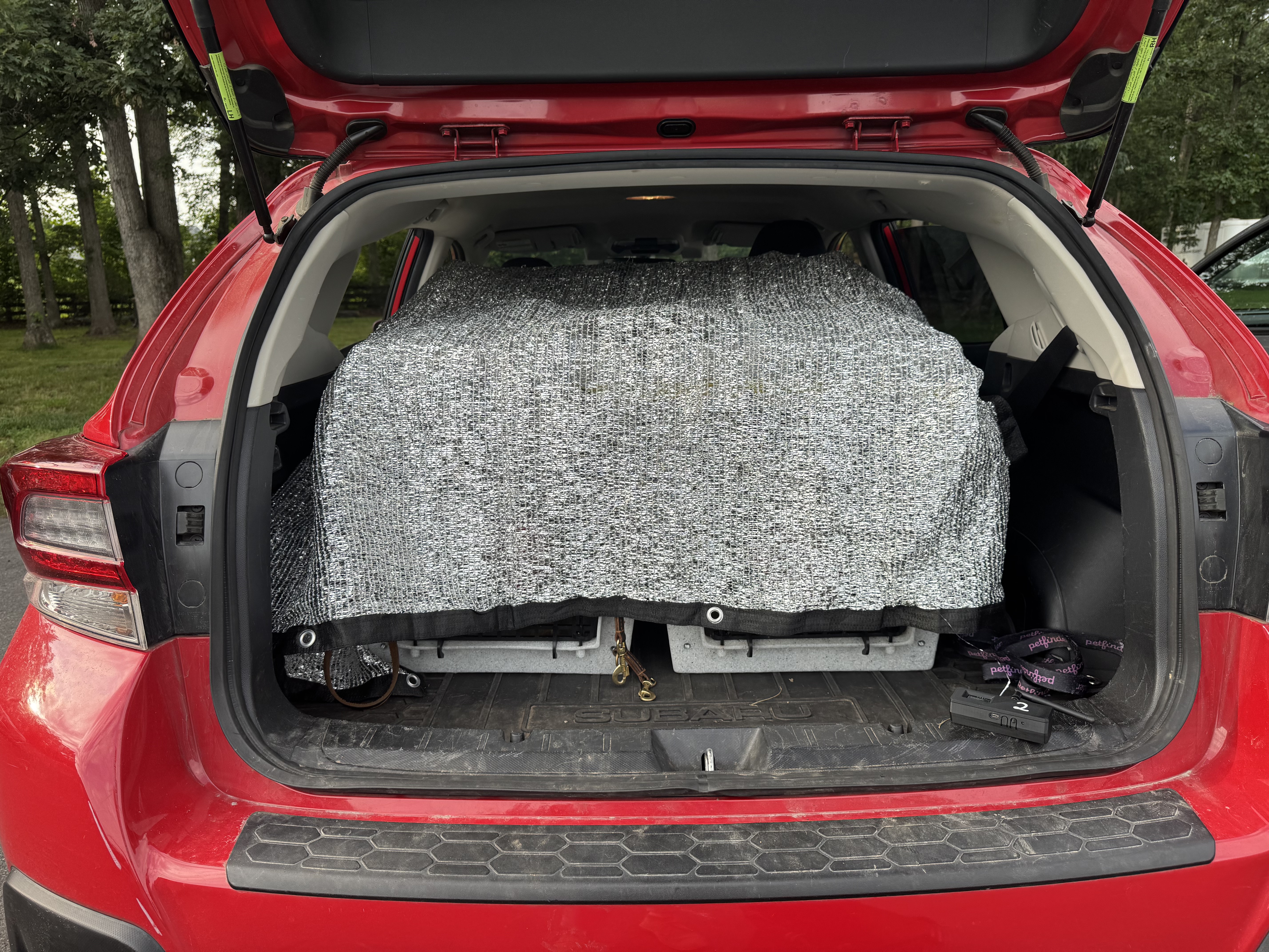
The monitoring node was placed under the blanket for a more accurate reading:
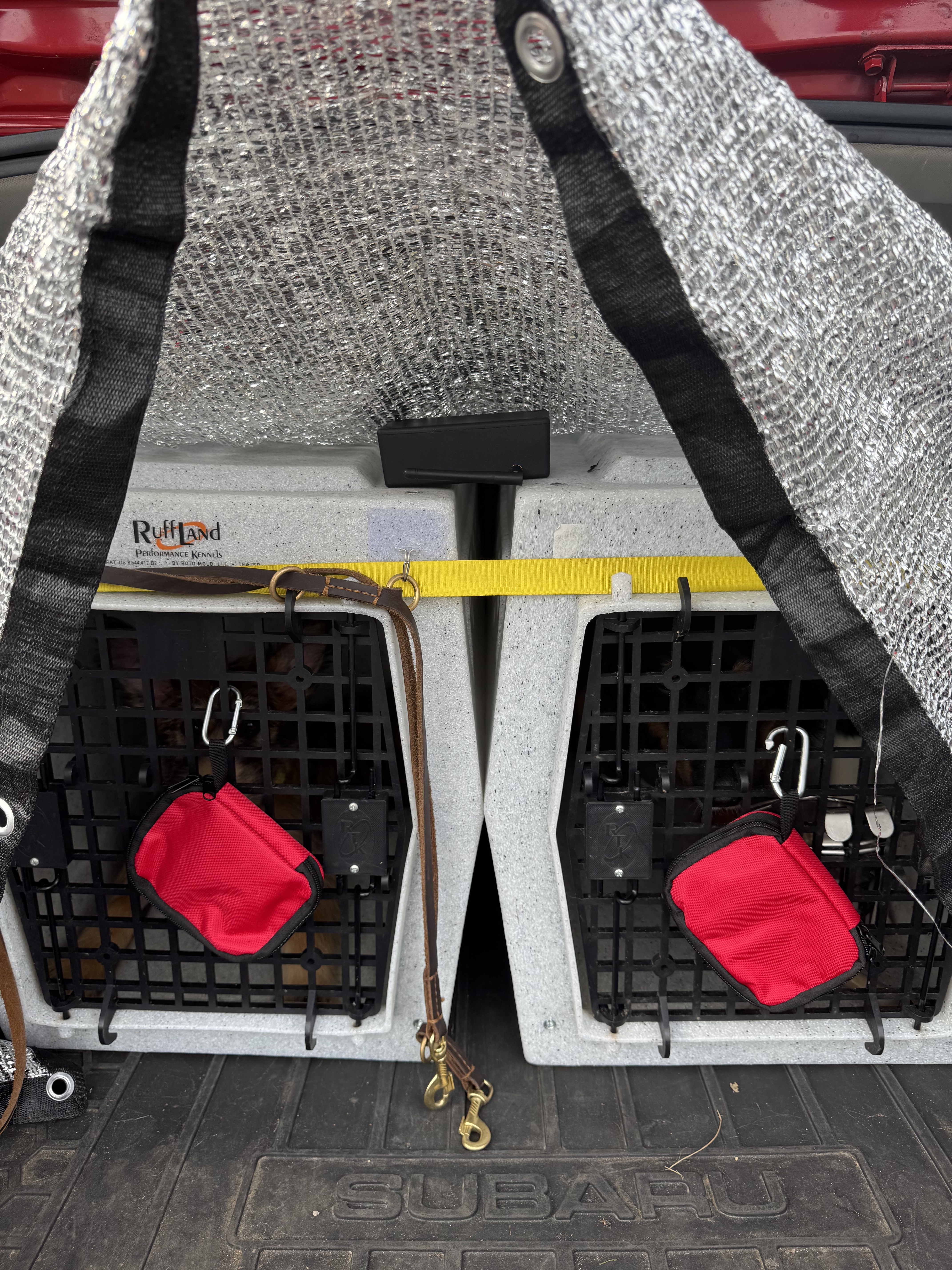
Battery life has been more than adequate so far with a continued monitoring session lasting 6 hours before the node being carried by the user died. I suspect that the user node, being an unmodified T-Beam, suffers from some parasitic draw and is more annoying to charge because of its micro-USB port. I would love to replace it with a SenseCap T1000-E, a consumer oriented Meshtastic device that has been praised for its ease of use and battery life. However, the T-Beam devices used for this project are using the old SX127x radios. As mentioned earlier, this would render the SenseCap boards useless to this project if they were paired with my existing T-Beam boards.
Next steps
To mitigate the issues with radio incompatibility and take advantage of the hardware improvements seen in newer Meshtastic devices, I may replace the T-Beam in the monitoring node with another device such as a XIAO board from Seed Studio or a RAK wireless device. Both would use newer radios and have improved battery life. I have also considered the possibility of making a custom RAK wireless add-on board using their published pinouts and dimensions. This is something that would make future iterations of this device easier to produce, but the up-front cost would be high. I imagine there are others that could benefit from a Meshtastic-mounted microcontroller of some kind, if that is you feel free to reach out.
For now I will wait for more user feedback and keep things as they are (e.g. not broken because of my meddling).