Making A Dog Training Button Board
- Date published: 2025-06-03
- Date updated: 2025-06-12
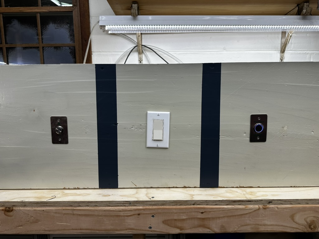
Having some tools and a space to work tends to attract odd jobs; as I see it, it is one of the major benefits of having such a space. Recently, I was asked to mount a few buttons and a light switch to a board for a dog trainer; it was a simple enough task and I had a wood scrap that was the perfect size laying around from a furniture restoration project, so I agreed. A while ago I was given an old RotoZip and I had been looking for an opportunity to use it. The buttons and switch were mounted relatively easily and the final (as far as I knew at the time) product was ready for delivery:
Electronics
Then, as with all simple jobs, the desire to complicate it by an order of magnitude struck me. I pitched the idea to the dog trainer: "what if it beeped?" And they were in. As a short aside about dog training, the speed of rewarding a dog (or any other animal, for that matter, including people) for a "good" action is directly linked to their future performance for that task. In other words, good behavior needs to be followed with a reward as quickly as possible for the best results in training. This is why many dog trainers will use clickers, the click is associated with a treat and with enough conditioning the click, which has no inherent positive value, becomes the reward. The click is significantly easier to use as an immediate bridge between the behavior and the reward than only producing a treat out of a pouch. By having your training apparatus create a tone when a correct action is performed, the dog is immediately knows they have performed the correct behavior without the delay of a trainer, and the behavior will be more likely to be linked to a reward by the dog. Read this article if you are curious to learn more, back to the actual point of this post.
My microcontroller of choice for projects like these tends to be the Pi Pico which hosts a RP2040 controller along with a 5v to 3.3v regulator. The form factor and price of the Pico are excellent for integrating into small places and it can be programmed in a wide variety of ways from MicroPython over a USB mass storage device interface to Rust over the integrated SWD interface. In terms of performance the RP2040 is lacking compared to its peers but the extensive documentation and community support generally make up for it. Still, two ARM cores and plenty of varied IO is more than enough for most projects, especially those that could be accomplished with discrete logic if I had the chips on hand.
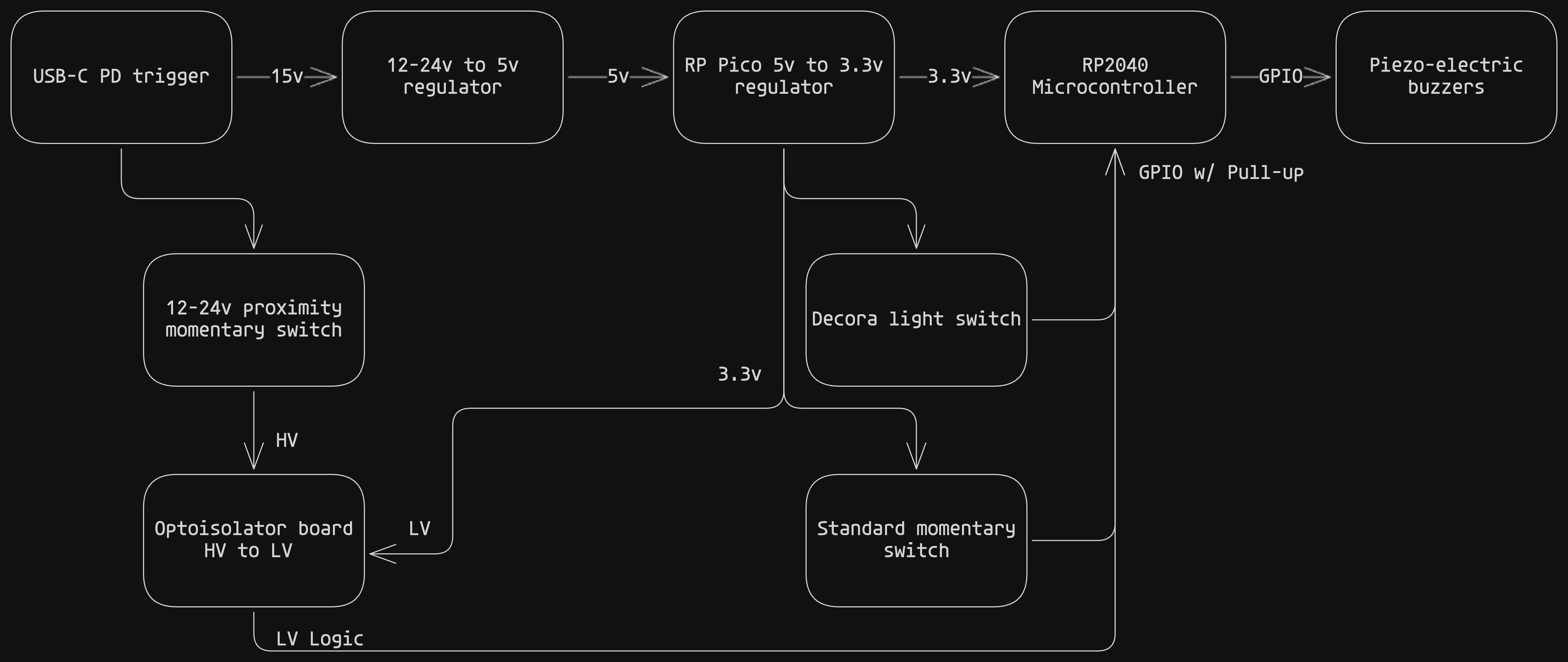
Two of the mounted switches, the light switch and the momentary switch, are simple open/closed circuit switches. They do not require any additional logic beyond checking if there has been a rising or falling edge. The third switch, however, is a proximity switch that required 12-24v to operate its internal logic. Generally, proximity switches work by generating a signal through a coil. The signal's characteristics are measured before and after this coil, and if the capacitance of that system is changed, say by a person made of primarily salty water standing nearby, a touch is registered. Obviously this system cannot operate without some known voltage to power this signal generation and measurement. I would need some kind of power supply that could provide 12-24v to the proximity switch and be stepped down to the 5-3.3v required by the Pico. The general scheme of how I accomplished this is below:
Because this would be a one-off project, I did not feel the need to spend time minifying or searching for the most efficient components for my application. Whatever I had in stock that would work is what I used. When working with 12-24v systems the first place I look for cheap consumer/hobby parts is the automotive space. There are many options for people looking to add a USB port to their vehicle or support some 5v device such as a GPS tracker. The power source for this whole board is a USB-C power delivery trigger board set to 15V. Power delivery is a very interesting tool but one issue I ran into was the AC/DC converter I purchased for this project, while it was advertised at 30W it was not capable of supplying 15V. I will not claim to be an expert on the USB-PD protocol but the general idea is that devices must supply their listed power when asked to do so but that does not mean they need to support higher voltages. There are specifications that power supplies of higher power ratings must delivery proportional voltages, however, at the end of the day if you are sending a project to someone less tech-savvy how can you expect them to understand that even though the ports fit together the project is not going to run because they didn't use the expensive USB-PD converter you sent along with the rest of the package. I got around this by semi-permanently affixing the USB-C cable to both the board and the power brick. That way nobody will be tempted to take that brick to charge their phone or anything like that.
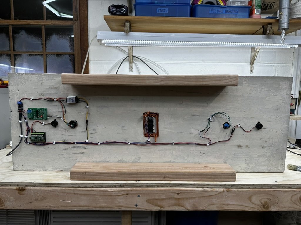
There was also a need to step down the 12v output from the proximity switch to 3.3v logic to be safe for the Pico, that was accomplished with a hobbiest level-shifting board powered by the Pico's own 3.3v regulator. Terminal blocks were used throughout to make assembly easier, the wiring could have been much more compact or perhaps constrained to a perf-board but I enjoyed laying out the electronics like an art project. The final layout is shown below:
Programming
There are a few ways to approach a program for something like this, starting from the top it generally looks like this:
- Hardware selection
- In the hobbiest space this is basically whatever you are feeling at the time, in the commercial space it is largely about cost, available IO, and tool availability in that order
- In this case the RP2040 controller on the Pi Pico board
- Language selection
- Often times you do not have an option and you will use whatever the manufacturer has put together, sometimes you get to pick between C and C++
- In this case the Pico can be programmed with C, C++, Python, Rust, and probably many other options not listed
- Approach selection
- This is a very general way of saying that you need to decide what you are going to program, this category is defined by things that cannot be changed with a simple refactor
- Examples include using an RTOS or using a particular toolchain
I enjoy programming in Rust and I already have a large number of sample projects on the RP2040 to pull from so that is what I selected for this. Because of the simple nature of this project, approach selection is not as critical but I prefer to use Embassy when possible due to its Async utility that takes much of the difficulty out of programming either an standard state-machine or RTOS driven codebase. Embassy is also great as it brings the plug-and-play nature of many Rust dependencies to the embedded world, making it easy to interface with peripherals or write compact code that would not necessarily in C/C++ without significant boilerplate. Of course, this comes at a cost, Embassy and Async in general takes a large amount of compiler overhead to be possible which is generally observed in poor compilation times and bloated binary blobs. In production this can be expensive and hard to justify, wanting to use the new shiny tool is rarely a good enough reason to pay for more on-board flash memory. Also, through limited bandwidth interfaces such as SWD, a large binary can take much longer than expected to upload. Some interfaces for more expensive chips can operate at high speeds such as commercial J-Link debuggers but that functionality is beyond the standard they are based on so their open-source counterparts can rarely compete.
The main loop of the code can be seen below:
let butt1 = Input::new(p.PIN_20, Pull::Down);
let butt2 = Input::new(p.PIN_19, Pull::Down);
let butt3 = Input::new(p.PIN_18, Pull::Down);
let get_state = || (butt1.is_high(), butt2.is_high(), butt3.is_high());

let mut beeper1 = Output::new(p.PIN_14, Level::Low);
let mut beeper2 = Output::new(p.PIN_15, Level::Low);

let mut last_state = get_state();
info!("Entering main loop CORE0");
loop {
    let state = get_state();
    info!("Button states: {:?}", state);
    if state != last_state {
        info!("State change, beeping then debouncing");
        beep(&mut beeper1, &mut beeper2).await;
        Timer::after_millis(DEBOUNCE_MS).await;
        last_state = get_state();
    }
    Timer::after_millis(50).await;
}
Because all that matters is that a button has changed state, the check can be relatively simple. Once a change is state is detected a beep is triggered which calls this function:
async fn beep(beeper1: &mut Output<'_>, beeper2: &mut Output<'_>) {
    beeper1.set_high();
    beeper2.set_high();
    Timer::after_millis(BEEP_DURATION / 2).await;
    beeper1.set_low();
    beeper2.set_low();
}
The beepers themselves are wired into two separate pins, mainly because I added the second one after the fact and did not want to do any more soldering. This application is not timing critical, so changing one after the other is acceptable. The values here are just chosen to sound good and were totally arbitrary. The rest of the code for this project is boilerplate for setting up the async runtime, if you are interested the code can be seen on my Git: https://github.com/Riceman2000/button-board
Final thoughts
This project was an enjoyable exercise and a great way to try out a few different components that I have been eying for awhile, such as the power delivery trigger boards. I hope to find an excuse to use the extras soon.